Bloodlight is an open-source (hardware and software) multispectral PPG research platform that Codethink is developing to research possible design improvements for medical devices.
One of the more challenging aspects of prototyping research hardware has always been the construction of plastic enclosures/cases. This is an even more fundamental issue for wearable/medical prototypes - in our example the case plays a strong role in the PPG sensor's optical properties.
Our second revision sensor was 200x more accurate than the initial prototype hardware, and this was only possible with the optical isolation that our black plastic case could provide.
Initial Case Design
We decided to design the case using OpenSCAD, primarily as we didn't have extensive experience using traditional 3D CAD modelling software. This type of software generally has a high learning curve, and OpenSCAD uses simple python-esque programmatic declarations and manipulations of 3D shapes to create models instead of manipulating them via a GUI.
The simple python-esque indications are advantageous for software engineers. It makes it easier for us as this has the familiar workflow of "type stuff, hit compile, things happen, when it's all good, commit the changes".
With OpenSCAD, it's also quick to produce something basic. However, it can be challenging to get the exact result you want. The tools available in OpenSCAD aren't as immediately powerful as those in traditional CAD programs - small tweaks can require a surprising amount of code. Inspecting the produced model can also be a little tricky - OpenSCAD provides a simple viewer, but no specific tools for measuring, etc.
Overall we think the choice of OpenSCAD still worked in our favour; we managed to get a basic case model produced reasonably quickly without having to learn unfamiliar tooling. When the responsibility for the case was given to another engineer, they were also quick to pick up and use OpenSCAD.
Case Design Workflow using OpenSCAD
Assuming the board’s design has already been finalised and is ready for a new case, this section will walk you through our process for designing a case from start to finish.
The source code for this project is available here >>, and these instructions will assume any shell commands are run from the root of this repository.
1. Export the PCB as VRML
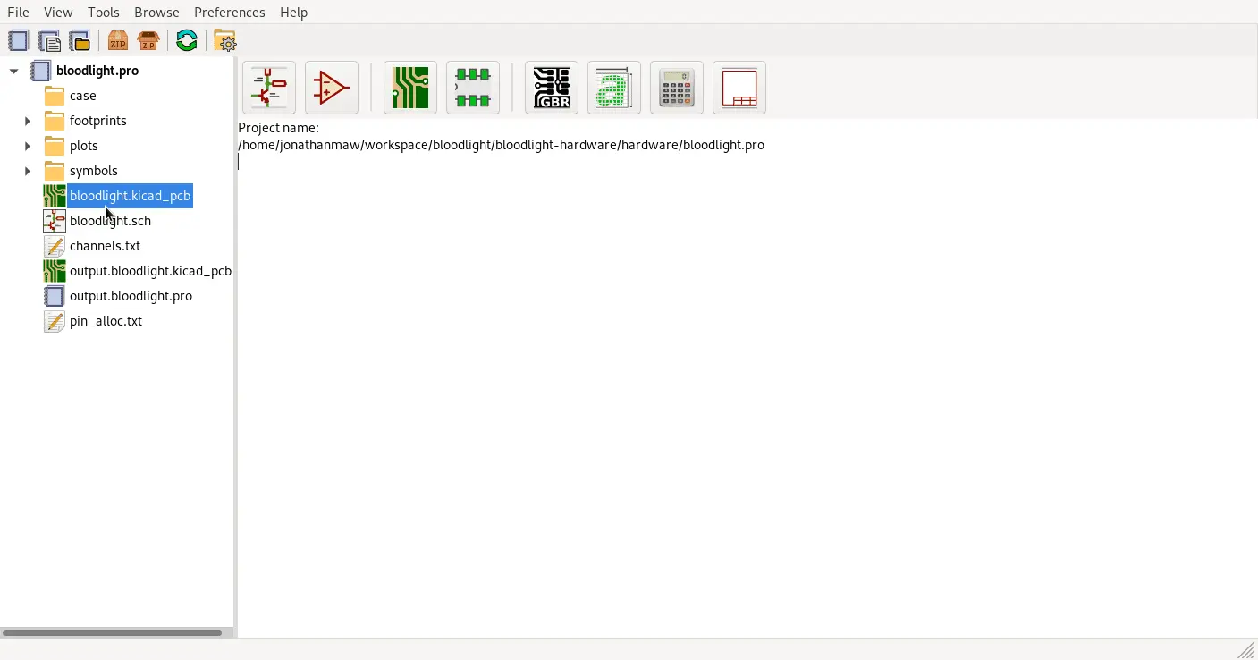
First, open up the pcb in KiCAD by running kicad bloodlight.pro
Once you have the board exactly as you like it, open up the PCB file:
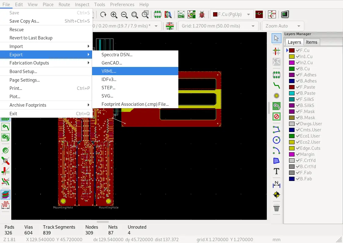
Then click File->Export->VRML
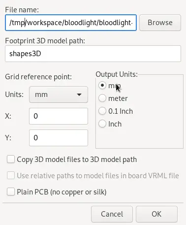
And make sure the grid reference units are mm, and the output units are mm
2. Convert the VRML to STL
We use Blender and a script written to use Blender’s built-in python interpreter to do an automatic conversion from VRML to STL.
It’s now a simple matter of running the command-line blender --background --python hardware/blender-wrl-to-stl.py -- hardware/bloodlight.wrl
3. View Case and Board in OpenSCAD
View the board and the case together in OpenSCAD (thanks to OpenSCAD being able to import from stl) cd hardware/case && openscad case.scad
To see the case and the board together, call the module “render_whole_assembly()”
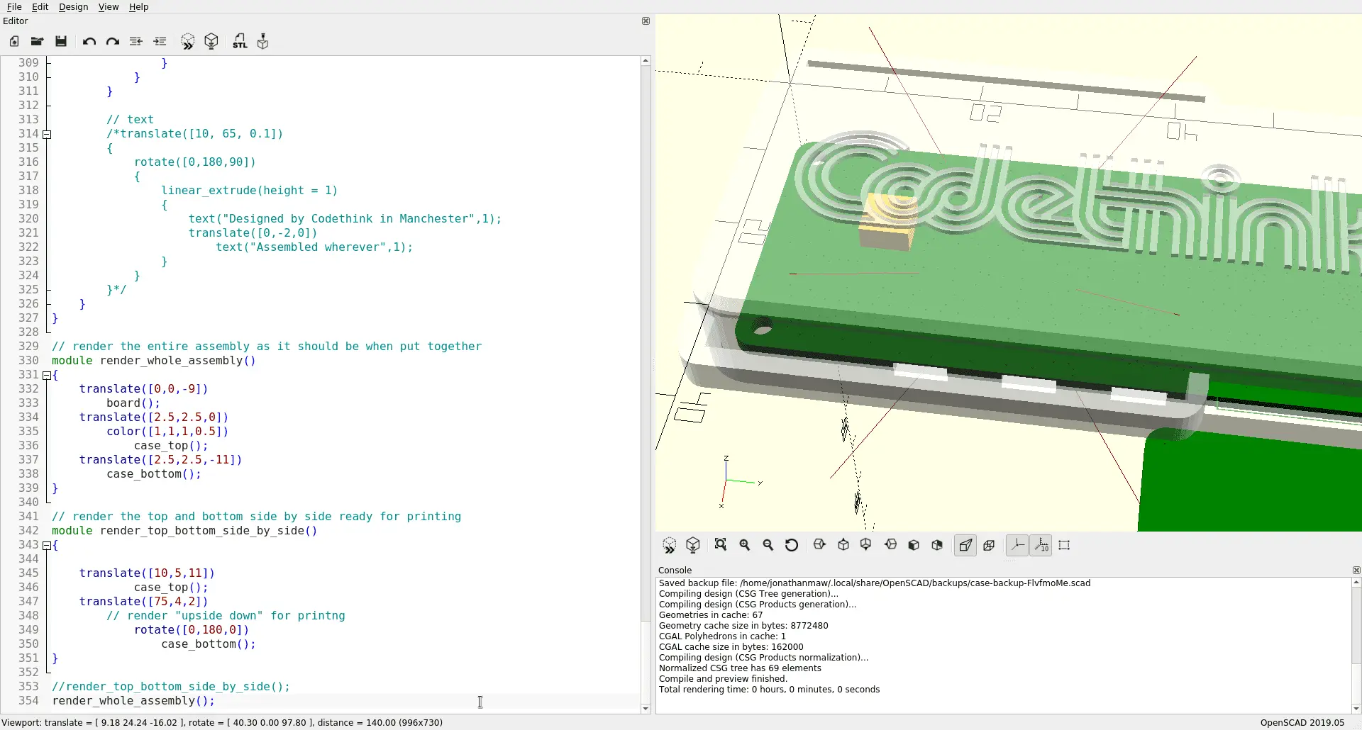
After you’ve made all the changes you want, edit the code, so it calls “render_top_bottom_side_by_side()” again, then renders it by clicking Design->Render or pressing F6
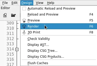
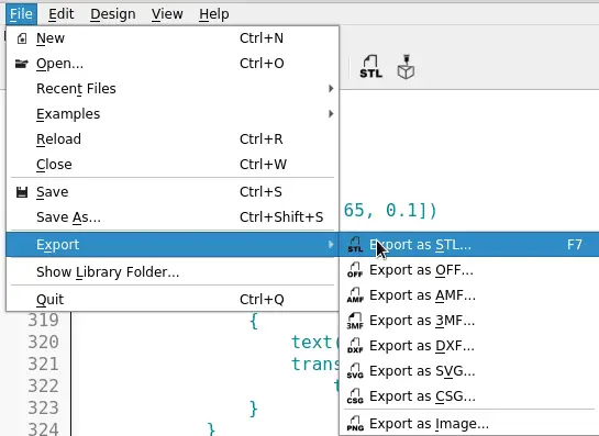
This will convert the case’s model from a collection of intersecting shapes into a single model. Once that has finished rendering, export the case as an STL by clicking File->Export->Export as STL…, or pressing F7.
4. Print the case
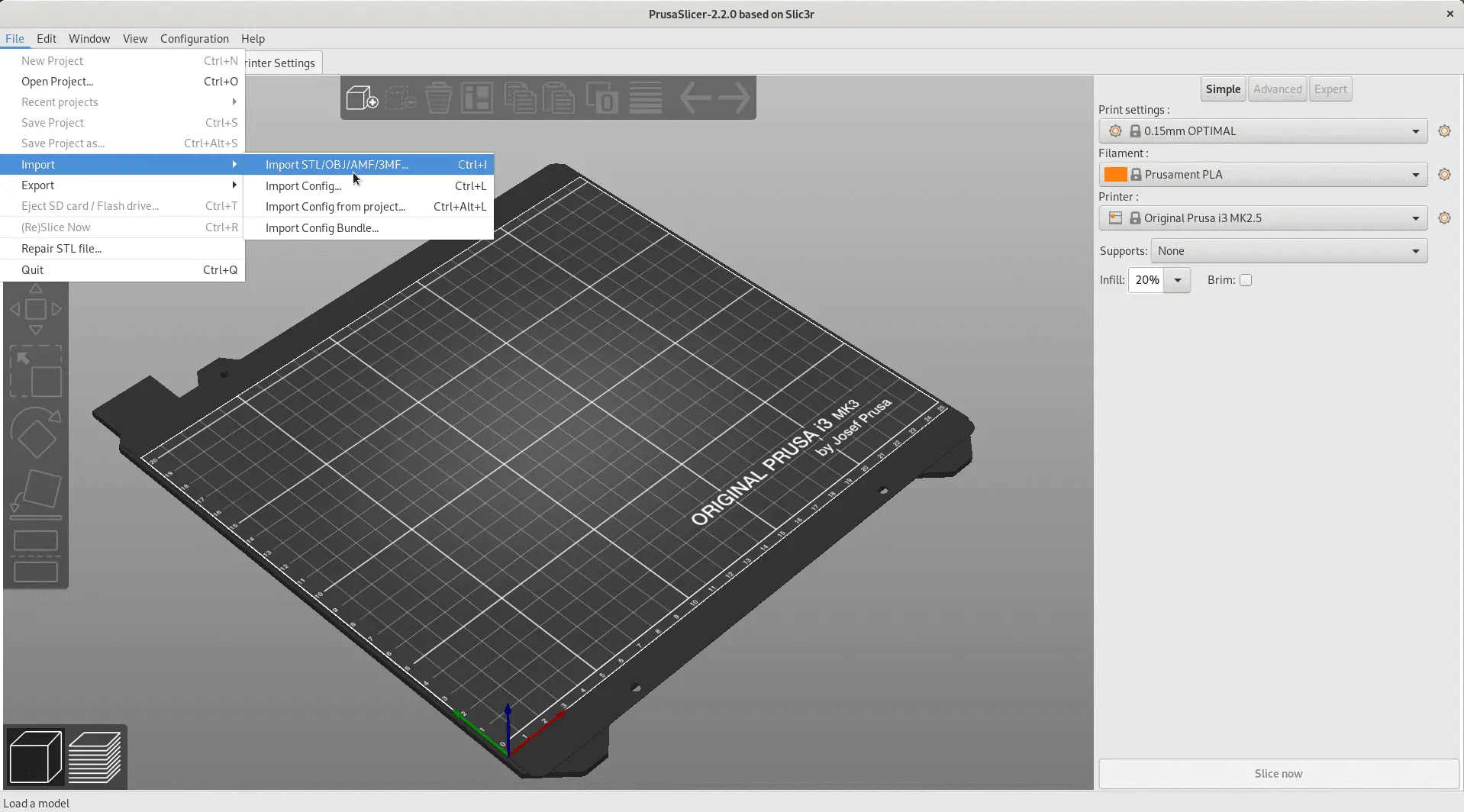
We use Prusa Slicer to convert our model to printing instructions, as it was designed for the brand of printer we use. Your printer may have its own recommended software or might be compatible with slic3r
Firstly, start your slicer software and import the STL (in PrusaSlicer, that’s File->Import->
Next, Slice the model to convert it into printing instructions.
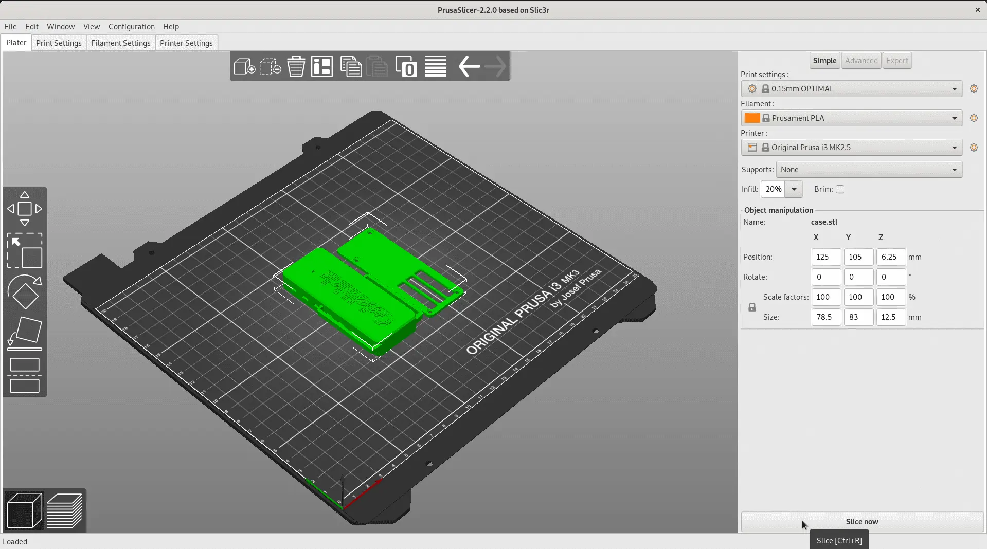
At this point, the slicing software will warn you if there are printability issues with your model, and it should show you how it will print each part of the model.
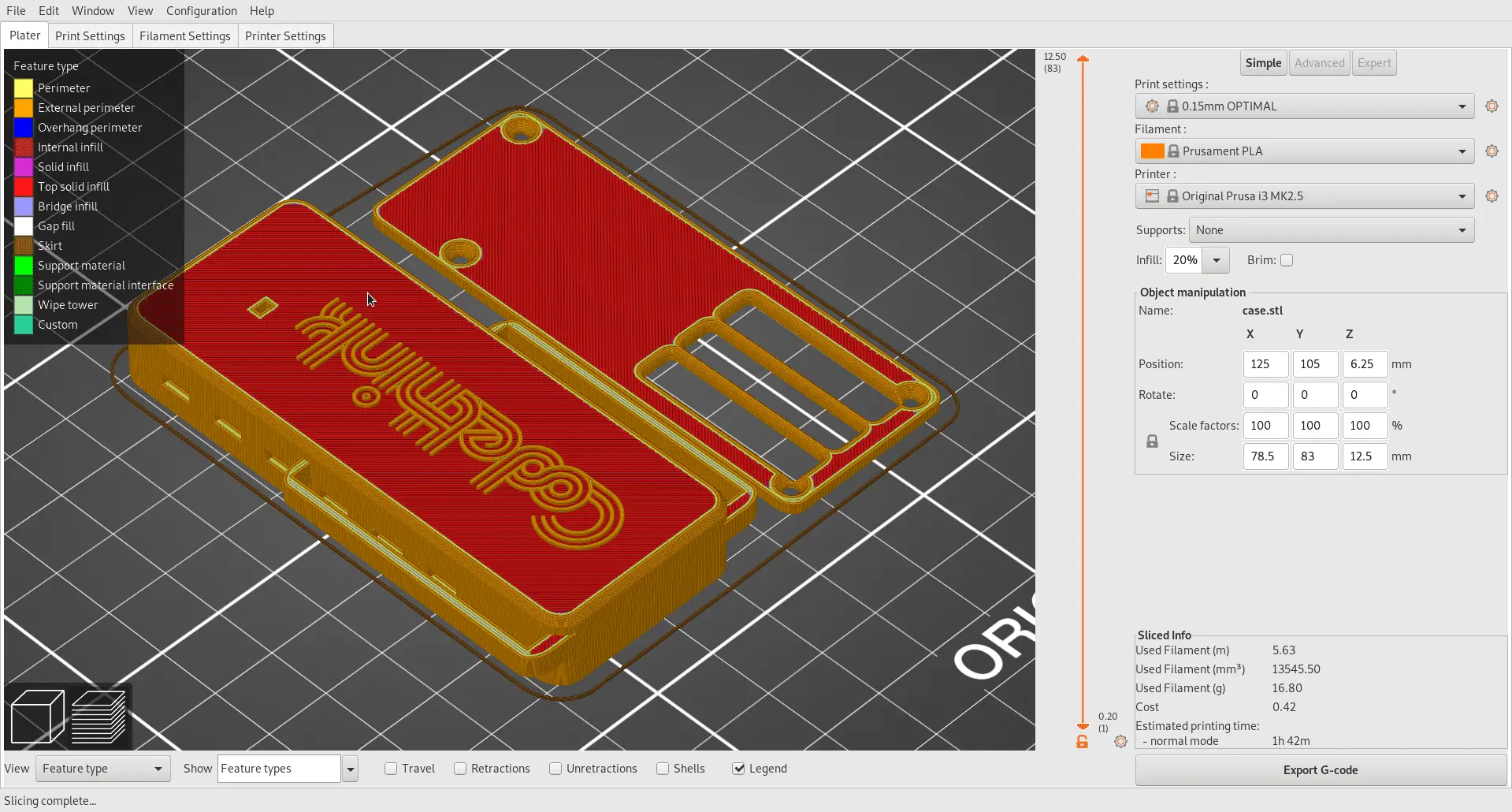
From here, you can print the model if your computer is connected to the printer (which should take a couple of hours), or generate G-Code to send to your printer by other means.
Misadventures
During our experiments with putting together the board and case, we ran into some pitfalls.
Firstly, and most importantly, the 3D model produced by KiCAD had inaccurate dimensions on several components or didn't place certain parts at all. The incorrect 3D model meant "keep out" areas weren't adhered adequately to on initial case prototypes, and we only discovered this when bringing the case and board together. The first couple of revisions of the board had some issues with connector alignment, etc. That might have been easier to resolve if we had boards to hand that we could measure with callipers in an office, rather than going off 3d data. Due to COVID-19, we worked from home and had to ship the hardware back and forth to each other.
Besides, some parts of our original design pushed the limits of what a hobbyist-grade 3D printer could handle. Our original logo was an SVG of the Codethink logo, but that proved complex and fine enough that the slicer software sometimes failed to translate it into printing instructions.
Another issue that guides how the case is designed is gravity. A layer of filament can lie on the previous layer, be held up by temporary support material (this can lead to some scarring of the surface when the support is removed, so it's best supported from the inside), or being held up by tension while bridging a gap. It can't overhang the edge of the previous layer by more than a certain extent, meaning that any shallow vertical gradients must be wider at the bottom than the top. Also, using support material marks the print's surface, so it's best only to have inside/bottom faces supported in this way.
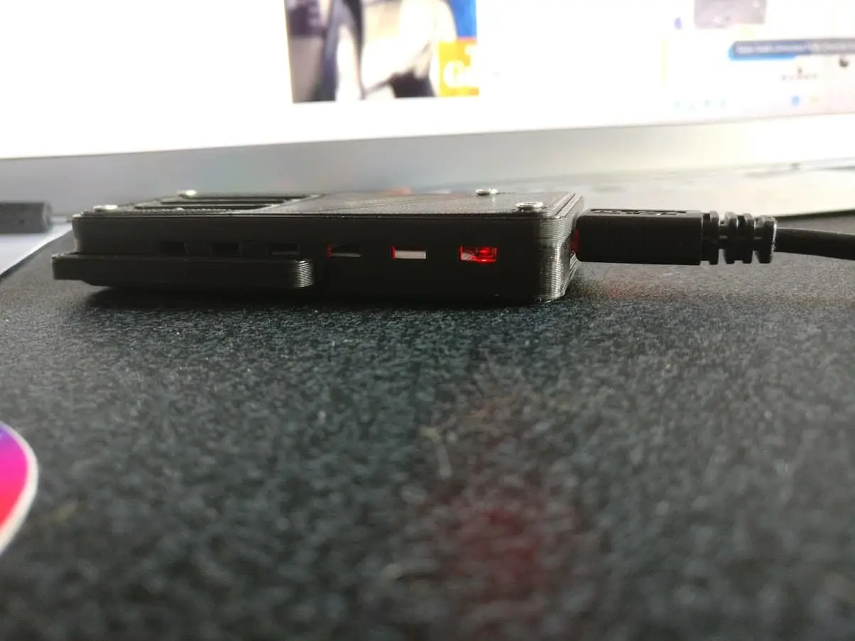
The final issue we discovered was that when using the device worn on the arm, the band exerted more pressure on the USB connector than you'd typically expect for a board that is only plugged in to charge or connect to a computer. We found that it was unfortunately relatively easy to exert enough pressure on the USB connector during measurements that the tab on the connector's back could snap rendering the connector and device unusable.
The board's micro-USB connector was likely designed for use in mobile phones, where it would be surrounded and supported by a moulded plastic, rather than being free-standing. The solution was to add support to the case's model, behind the micro-USB connector.
Finding where the support lies in the case is relatively simple, it sits in some holes drilled into the circuit board, seen as the two larger circular holes side-by-side in this picture:
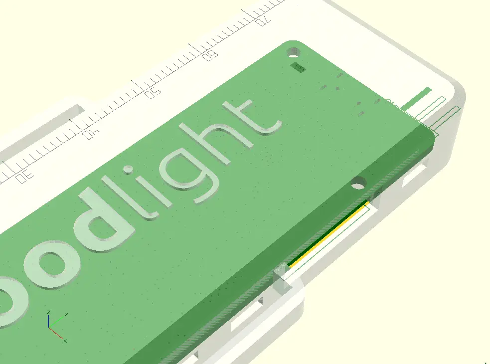
Relating the position of the holes to where the back of the connector is was harder. Also, it involved deciphering which dimensions to use on the datasheet for the connector.
Unfortunately, while these measurements left enough space for the connector to fit in the case, it failed to leave enough room to slide the connector into position.
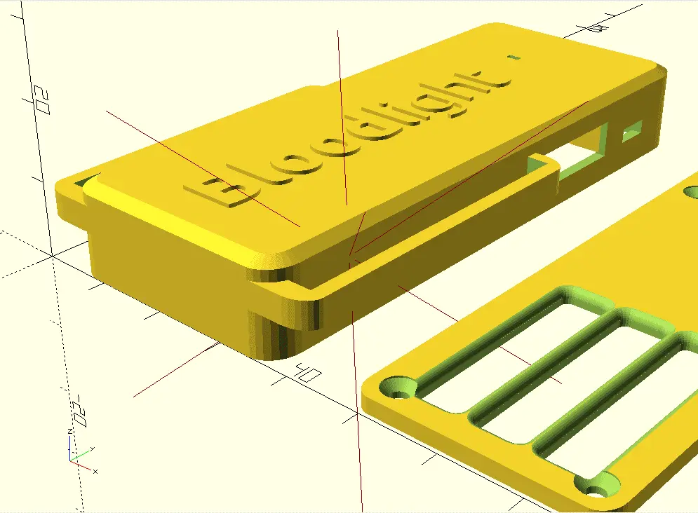
The Evolution of the Case
One of the most valuable features of using OpenSCAD to make the case is that it meshes well with version control tooling, allowing us to spin changes into different branches, and easily track what differs between versions. For example, this is what the case looked like in the first commit made public:
From there, we noticed that light was leaking into the photodiodes because the straps at the bottom pushed the case up slightly, so we moved the wings for the straps to the top of the case (see commit).
With the straps resolved, our next issue was the screws holding the case together standing out from the bottom of the case. Since the case is meant to be pressed against bare skin there, this was an irritant we wanted to remove.
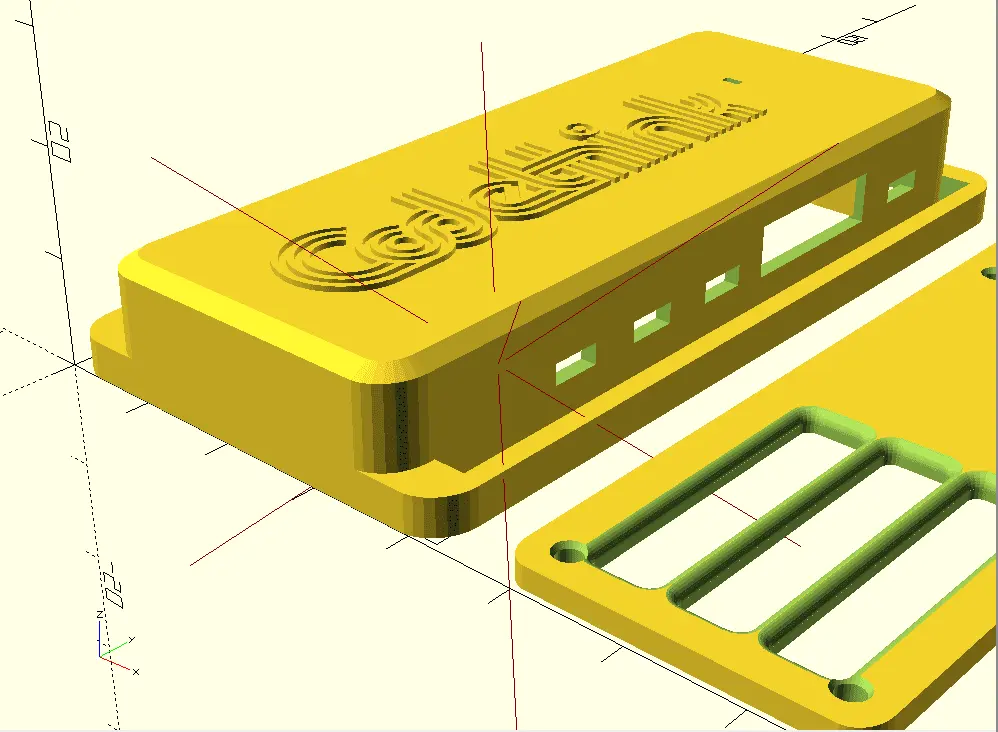
Our first attempt modelled the screw as a cone and a rod and then subtracted that from the case, by using countersunk screws

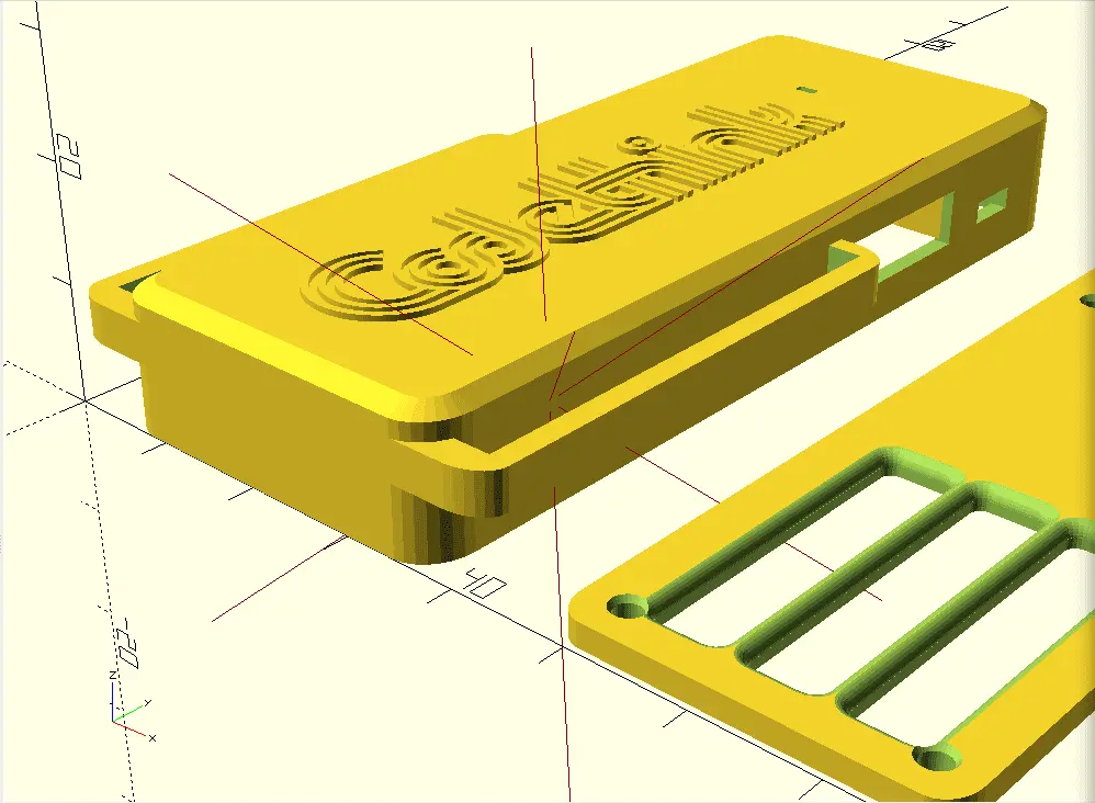
The first attempt still left part of the screw sticking out of the case, which we fixed in a second attempt by modelling another cylinder at the wide end of the cone.
Final thoughts
Designing a case design for Bloodlight was a new challenge for us. Previously our experience with case design was applying knowledge from various hobby projects. We learned that there’s no substitute for having a physical model to handle to make sure something fits together securely and comfortably.
We faced a few difficulties during the process, such as underestimating the stresses placed on the USB connector, but we could adapt and overcome them while producing a prototype.
As mentioned before, OpenSCAD is more comfortable for software engineers to use than other traditional 3D CAD modelling software. It uses simple python-esque programmatic declarations, and even though it was a first time for most engineers working with OpenSCAD, we designed a case that fit closely and comfortably on the forearm, reducing background light noise significantly.
Stay up to date on our latest news about embedded
Receive our most relevant Embedded stories in your inbox.
Related blog posts:
- More about Bloodlight: Bloodlight: A Medical PPG Testbed >>
- Improving the medical industry: The Case For Open Source Software In The Medical Industry >>
Other Content
- Assessing the reproducibility workflow in freedesktop-sdk
- Deep Dive into Upstream RISC-V Boot Chain
- Porting an Automotive Operating System to RISC-V
- Understanding Codethink's IEC 61508 Mapping for the Eclipse Trustable Software Framework
- Resisting Hyrum's Law with Private Constructors in Python
- FOSDEM 2026
- Building on STPA: How TSF and RAFIA can uncover misbehaviours in complex software integration
- Adding big‑endian support to CVA6 RISC‑V FPGA processor
- Bringing up a new distro for the CVA6 RISC‑V FPGA processor
- Externally verifying Linux deadline scheduling with reproducible embedded Rust
- Engineering Trust: Formulating Continuous Compliance for Open Source
- Why Renting Software Is a Dangerous Game
- Linux vs. QNX in Safety-Critical Systems: A Pragmatic View
- Is Rust ready for safety related applications?
- The open projects rethinking safety culture
- RISC-V Summit Europe 2025: What to Expect from Codethink
- Cyber Resilience Act (CRA): What You Need to Know
- Podcast: Embedded Insiders with John Ellis
- To boldly big-endian where no one has big-endianded before
- How Continuous Testing Helps OEMs Navigate UNECE R155/156
- Codethink’s Insights and Highlights from FOSDEM 2025
- CES 2025 Roundup: Codethink's Highlights from Las Vegas
- FOSDEM 2025: What to Expect from Codethink
- Codethink/Arm White Paper: Arm STLs at Runtime on Linux
- Speed Up Embedded Software Testing with QEMU
- Open Source Summit Europe (OSSEU) 2024
- Watch: Real-time Scheduling Fault Simulation
- Improving systemd’s integration testing infrastructure (part 2)
- Meet the Team: Laurence Urhegyi
- A new way to develop on Linux - Part II
- Shaping the future of GNOME: GUADEC 2024
- Developing a cryptographically secure bootloader for RISC-V in Rust
- Meet the Team: Philip Martin
- Improving systemd’s integration testing infrastructure (part 1)
- A new way to develop on Linux
- RISC-V Summit Europe 2024
- Safety Frontier: A Retrospective on ELISA
- Codethink sponsors Outreachy
- The Linux kernel is a CNA - so what?
- GNOME OS + systemd-sysupdate
- Codethink has achieved ISO 9001:2015 accreditation
- Outreachy internship: Improving end-to-end testing for GNOME
- Lessons learnt from building a distributed system in Rust
- FOSDEM 2024
- QAnvas and QAD: Streamlining UI Testing for Embedded Systems
- Outreachy: Supporting the open source community through mentorship programmes
- Using Git LFS and fast-import together
- Testing in a Box: Streamlining Embedded Systems Testing
- SDV Europe: What Codethink has planned
- How do Hardware Security Modules impact the automotive sector? The final blog in a three part discussion
- How do Hardware Security Modules impact the automotive sector? Part two of a three part discussion
- How do Hardware Security Modules impact the automotive sector? Part one of a three part discussion
- Automated Kernel Testing on RISC-V Hardware
- Automated end-to-end testing for Android Automotive on Hardware
- GUADEC 2023
- Embedded Open Source Summit 2023
- Full archive